This project is taken from our 6 person 3rd year master's group project which can be found here
|
The Platform Node in our system is used to transport the workpieces between nodes and are 4 wheel drive robotic rovers equipped with Mecanum wheels capable of omni-directional travel. These rovers are used as a base for the robotic manipulator which carries, manipulates and positions the workpieces on the processing nodes. They are controlled by embedded microcontrollers and are equipped with a raspberry pi for wireless communication via WiFi in order to receive commands from the Control Node on when, where and how to move. |
|
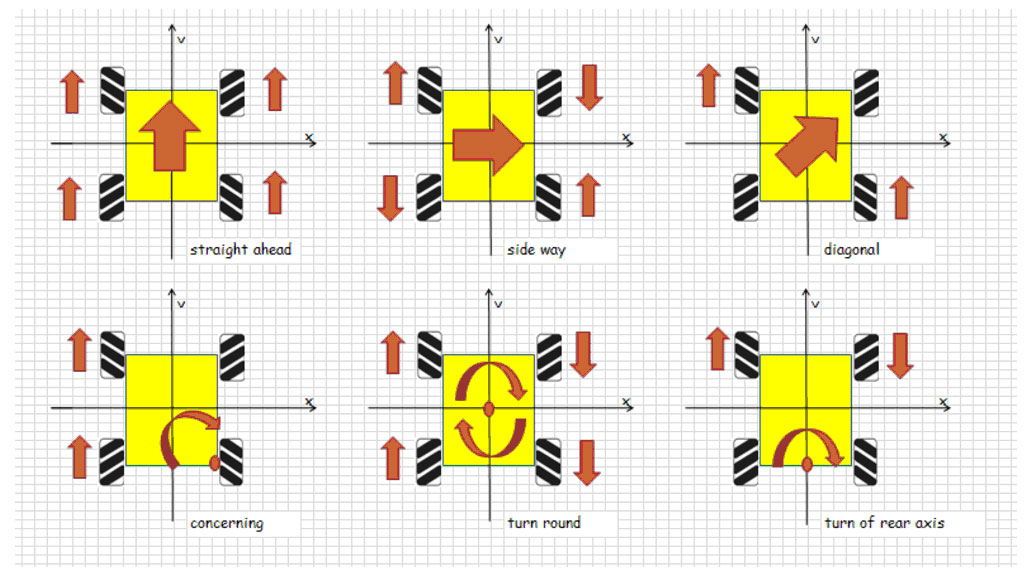
Transport Platforms are used in many industrial applications where material handling and data collection is required in order to safely find, track, and move anything from parts to pallets in warehouses, factories, and distribution centers. We sought to emulate this functionality with the mobile platforms provided using them to transport the workpiece from one station to the next leveraging the added dexterity provided by their Mecanum wheels as would be used on a production line. The stand out feature of the provided platforms are indeed their mecanum wheels. Mecanum wheels are conventional wheels with a series of rollers attached to its circumference. These rollers typically each have an axis of rotation at 45° to the plane of the wheel and at 45° to a line through the centre of the roller parallel to the axis of rotation of the wheel. These wheels allow robots and other vehicles to move in any direction while keeping the front of the robot in a constant pose orientation. This is achieved by causing the vector of motion for each wheel to act at a 45° angle to the vertical plane, then depending on the wheel activation sequence, command over translational motion in addition to standard forwards and backwards motion is provided. Due to this feature, mecanum wheel are popular in cases where precise maneuvering is required, such as in industrial vehicles like forklifts and transport platforms. |
Requirements |
|
The Platform |
|
These are 4 wheel drive, Mecanum wheeled mobile platforms vehicles that can be made to move in any direction and turn by varying the direction and speed of each wheel. Each platform is 40cm X 36cm X 10cm in dimension and is made from a composite aluminium alloy |
|
Each Platform consists of 4 12 volt Geared DC motors with rotary encoders for position and velocity feedback, controlled by an Arduino Mega 2560 R3 board powered by the Atmel ATmega2560 microcontroller. |
|
Additionally, The wireless communication for this Node is provided via a Raspberry Pi 3 B+ connected over WiFi to ROS communication architecture, this allows it to connect and feed data back to the main control node which holds the ROS master. The whole assembly is then powered by a single 12V 1800mAh NiMh (Nickel Metal hydride) battery. In order for the platform to be reliably detectable by our visual systems’ algorithm, it is fitted with bright red balls in a triangular configuration. This allow the vision system to detect to constantly detect the pose of the vehicle, which through our ROS communication system, posts the position data on to a topic which the platform subscribes to and then implements feedback control taking the platforms to their desired target locations in the arena and optimising the path over time. |
|
Our system was initially supposed to consists of 2 platforms where one platform was to be used as a mobile product bin, this was dropped due to time constraints. Instead there is only only one base mobile unit for the Robotic Arm. Transporting the arm and workpiece, from the node to node, and will them transport the finished piece or set of finished pieces to the collection/storage bin. Accomplishing this required heavy use of the omni-directional motion provided by the Mecanum wheels. In order to properly utilise these wheels the motors need to be activated in a set sequence according to this layout. |
 |
Control System |
|
To ensure accuracy and consistency in tracking the desired reference points created by the vision system and thus overall systems performance, there are 6 closed-loop feedback loops present on the platform. 4 low level PID loops on each wheel based in the Arduino and 2 high level bang-bang controllers based in the Raspberry Pi ROS Node script, one for the pose angle and another for the Linear Distance between the current and desired position of the vehicle. PID control the most common control for of control system implementation. Most practical feedback loops are based on PID control or some variations There off. The Classical Form of a PID controller is: |
|
\begin{equation} u(t) = K_p e(t) + K_i \int_{0}^{t}e(t) + K_d \frac{d e(t)}{dt} \end{equation} |
|
where u is the control signal and e is the control error (e = reference r - output y). The reference value is also called the setpoint. The control signal is thus a sum of three terms:
The controller parameters are proportional gain k, integral gain ki and derivative gain kd. Through appropriate application of this controller it is possible to maintain a system state at a specific value despite any disturbances it might encounter. Such as with maintaining the same constant velocity in all the wheels to ensure the vehicle moves as desired with minimal drift and maintain a consistent performance regardless of external disturbances. Each wheel has its own Velocity feedback system by first converting the encoder angular position in counts, C, into angular velocity in counts per second, C/s, the angular velocity of each wheel. |
                        int pid::velocity(int pos, long tim)
                        {
                            //calculate the rotational velocity from encoder counts
                            Velocity = (pos - prevPos)/tim;
                            prevPos = pos;
                            return(Velocity);
                        }
|
This value is then fed into the PID loop with the set point set by the High Level controller.The low level controller then calls functions which changes the direction of actuation based on the commands send from the high level controller. These actions are then determined by a state machine which switches between trying to minimise the Angular pose error and the Linear Displacement error depending on high level commands given. The Angular Position State controller is given below: |
                        if(state == 0) //First State which controll the angular position
                        {
                            int aCmd = ros.Vel[0]; //Read velocity command from high level controller
                            int act = ros.Vel[1]; //Read change of state command
                            if(act == 1 ) //if state is angular velocity
                            {
                                if (aCmd>0) //Rotate Right if command is is > 0
                                {
                                    motor.rotateRight(aCmd,timeBetFrames,M1encoderPos,M2encoderPos,M3encoderPos,M4encoderPos);
                                }
                                else if(aCmd<0) //Rotate Left if command is is < 0
                                {
                                    motor.rotateLeft(-1*aCmd,timeBetFrames,M1encoderPos,M2encoderPos,M3encoderPos,M4encoderPos);
                                }
                            }
                            else //Otherwise stop the mottors and switch to Linear Displacement State
                            {
                                motor.Stop();
                                state = 1;
                            }
                        }
ROS Node |
|
The High level controller consist of the ROS Node and the Bang Bang feedback controller. The ROS node subscribes to the topic where the vision system posts and receives a path, which has been plotted around any obstacles present in the work area, as well as position data from the vision system. The controller then moves from point to point in the path and for each point it calculates the vector components from the current position of the vehicle to that point. It then separates this out into its angular and linear components. |
                        # create complex next position
                        nextPos = x[PtIndex]+y[PtIndex]*1j
                        pub.publish("next pos:" + str(nextPos))
                        # create complex current position
                        currentPos = PosX+PosY*1j
                        pub.publish("currentPos:" + str(currentPos))
                        # create error vector --> this gives Xerr and Yerr
                        currentPosError = nextPos-currentPos
                        pub.publish("currentPosError:" + str(currentPosError))
                        Xerr,Yerr = currentPosError.real,currentPosError.imag
                        # take arg of error vector and subtract alpha
                        desiredAlpha = np.angle(currentPosError)*100
                        pub.publish("InitialDesiredAlpha: " + str(desiredAlpha))
|
These values are then feed into the 2 Bang-Bang controllers starting with the pose angle. This checks to see if it is within a particular threshold and if it is greater than that, move one way, and if it is less than that move the other until is is with that threshold, with the position constantly being updated by vision system. This functionality is partially displayed below: |
                        if (alphaError > 5 and alphaError < 309):#In centi-rad
                            #rotate anticlockwise
                                try:
                                    NewCommand = str(RotSpeed)+",1\n"
                                    pub.publish(str(RotSpeed)+",1")
                                if (NewCommand != Command):
                                    arduino.write(NewCommand)
                                    #(Speed CCW,Rotate)
                                Command= NewCommand
                                except:
                                    pass
                            elif (alphaError < -5 and alphaError > -309):
                            #rotate clockwise
                                try:
                                    NewCommand = str(-RotSpeed)+",1\n"
                                    pub.publish(str(-RotSpeed)+",1")
                                if (NewCommand != Command):
                                    arduino.write(NewCommand)
                                    #(Speed CW,Rotate)
                                    Command= NewCommand
                            except:
                                pass
|
This is a simple form of feedback control which is activated to keep the desired value with an operable set range. This same procedure is then replicated for the Linear Distance Feedback. One advantage of this method over a more complex controller like a PID is its ease of development and implementation. However, a massive disadvantage of this method over a more complex controller is its lack of finesse in achieving desired targets. This leads to jerky oscillatory motion and reduced the accuracy, precision and repeatability of the system overall. Additionally, as part of our final system demonstrator we created an additional processing node which consists of LEDs, an arduino Uno R3 board and a Raspberry Pi 3 B for wireless connectivity attache to a foam board stand which lights up when presented with the workpiece. This was done in order to show the modularity of our system and the flexibility/expandability it allows. |